The design of the parts of the locomotive engine proper, like that of the boiler, is a subject which cannot be handled properly in the space allotted in this book. These designs are the result of a gradual development of the proper proportions based upon the tests of each part in actual service. The specifications for materials and workmanship are rigidly drawn and as carefully lived up to, for in railroad service the chances for failure of any part of the engine, because of the excessive vibration, are many, and the destructive effect of such failure is out of all proportion to the original manufacturing expense. These conditions, therefore, make perfect action and excessive reliability prime necessities in engine design. A few formulas, for the most part based on rational assumptions, are presented for the calculation of some of the most important parts.
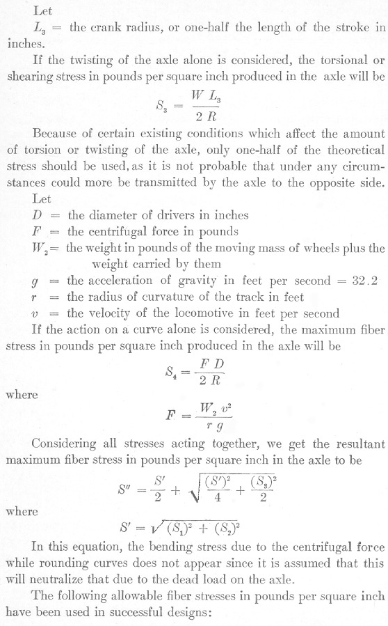
Axles. The stress in the axles is combined in many ways. The principal stresses are, first, bending stresses due to the steam pressure on the piston; second, bending stresses due to the dead weight of the engine; third, torsional or shearing stresses due to unequal adhesion of the wheels on the rails; and fourth, bending stresses due to the action of the flanges on the rails while rounding curves. Let


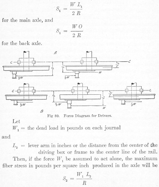
If there are only two pairs of drivers, the force W will be equally distributed between the crank pins as shown in A, Fig. 89.
If the force W, the total steam on the piston, is assumed to act alone, the maximum fiber stress in pounds per square inch produced in the axle will be


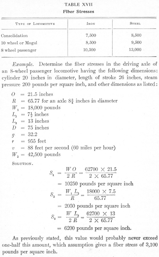
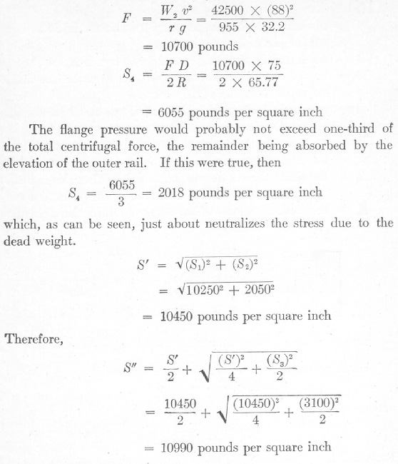
Therefore, an 8¾ steel axle is large enough for an 8-wheel passenger locomotive since the allowable fiber stress of 13,000 pounds per square inch is not exceeded.
If the locomotive under consideration was one having three pairs of drivers instead of two, the total piston pressure would be distributed as shown in B, Fig. 78.
 Back to the FAQ Page
