where
t = thickness of cylinder wall in inches
p = pressure in pounds per square inch
d = diameter of cylinder in inches
f = safe fiber stress which for cast iron is usually taken at 1500 pounds per square inch
For cylinder heads, the following empirical formula may be used in calculating the thickness:

where
T = the thickness of the cylinder head in inches
p = boiler pressure in pounds per square inch
d = diameter of stud bolt circle
Cylinder specifications usually call for a close grain metal as hard as can be conveniently worked. The securing of the proper proportions of a cylinder for a locomotive is a matter of great importance in locomotive design. The cylinders must be large enough so that with a maximum steam pressure they can always turn the driving wheels when the locomotive is starting a train. They should not be much greater than this, however, otherwise the pressure on the piston would probably slip the wheels on the rails. The maximum force of the steam in the cylinders should therefore be equal to the adhesion of the wheels to the rails. This may be assumed to be equal to one-fourth of the total weight on the driving wheels. The maximum mean effective piston pressure in pounds per square inch may be taken to be 85 per cent of the boiler pressure.
As the length of the stroke is usually fixed, by the convenience of arrangement and the diameter of the driving wheels, a determination of the size of the cylinder usually consists in the calculation of its diameter. In order to make this calculation, the diameter of the driving wheels and the weight on them, the boiler pressure, and the stroke of the piston must be known. With this data, the diameter of the cylinder can be calculated as follows:
The relation between the weight on the drivers and the diameter of the cylinder may be expressed by the following equation:

where
W = the weight in pounds on drivers
d = diameter of cylinders in inches
p = boiler pressure in pounds per square inch
L = stroke of piston ininches
D = diameter of drivers in inches
C = the numerical coefficient of adhesion
From the above equation, the value of d may be obtained since the coefficient of adhesion C may be taken as .25. The equation then becomes

from which

Example. What will be the diameter of the cylinders for a locomotive having 196,000 pounds on the drivers, a stroke of 24 inches, drivers 63 inches in diameter, and a working steam pressure of 200 pounds per square inch?

The above formula gvies a method of calculating the size of cylinders to be used with a locomotive when the steam pressure, weight on drivers, diameter of drivers, and stroke are known. This formula is based upon the tractive force of a locomotive or the amount of pull which ibis capable of exerting.
The tractive force of a locomotive may be defined as being the force exerted in turning its wheels and moving itself with or without a load along the rails. It depends upon the steam pressure, the diameter and stroke of the piston, and the ratio of the weight on the drivers to the total weight of the engine, not including the tender. The formula for the tractive force of a simple engine is

where
T = the tractive force in pounds
d = diameter of cylinders in inches
L = stroke of the piston in inches
D = diameter of the driving wheels in inches
p = boiler pressure in pounds per square inch
When indicator cards are available, the mean effective pressure on the piston in pounds per square inch may be accurately determined and its value p1, may be used instead of .85 p, in which case the formula becomes

Some railroads make a practice of reducing the diameter of the drivers D by 2 inches in order to allow for worn tires.
In the case of a two-cylinder compound locomotive, the formula for tractive force is

where
D = the diameter of the drivers in inches
d1, = diameter of low-pressure cylinder in inches
d2, = diameter of high-pressure cylinder in inches
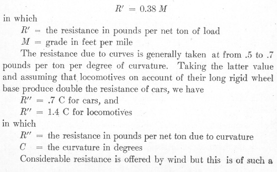
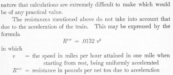
Train Resistance. The resistance offered by a train per ton of weight varies with the speed, the kind of car hauled, the condition of the track, journals and bearings, and atmospheric conditions.
Taking the average condition as found upon American railroads, the train resistance is probably best represented by the Engineering News formula

in which
R = the resistance in pounds per net ton (2000 pounds) of load
S = speed in miles per hour
The force for starting is, however, about 20 pounds per ton which falls to 5 pounds as soon as a low rate of speed is obtained. The resistance due to grades is expressed by the formula


 Back to the FAQ Page
